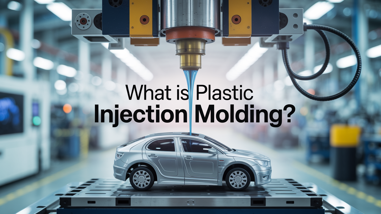
Plastic Injection Molding
Plastic Injection Molding turns plastic pellets into precise parts at speed. The machine melts the material, injects it into a shaped mold, cools it, and ejects a finished piece. You get repeatable quality and low unit cost once the mold is built.
If you’re new, the ideas are simple, but the choices matter. What happens inside the press? Which plastics fit your part? How do design details like wall thickness or draft affect cost and finish? And what timeline should you plan before your first good parts ship?
This guide gives you clear answers. You’ll learn the steps in the cycle, the key machine and mold parts, common materials, core design rules, typical costs, and how to avoid defects. By the end, you’ll know enough to plan a safe first run and hold a confident talk with any molder.
What Is Plastic Injection Molding And Why Is It Used?
It’s a high‑volume method that makes many identical parts with tight control. Molten plastic fills a metal mold, cools, and takes the exact shape, again and again.
Everyday Uses of Molded Parts
Look at a phone case, a car console, a toothbrush handle, or a game controller. Each uses a rigid shell with fine detail, steady color, and a clean surface. Injection molding shines when you need the same part thousands or millions of times with the same geometry. Once the mold is ready, the press repeats the cycle with little drift in size or texture. That repeatability supports accessories, consumer goods, medical disposables, and interior trim where feel and fit matter as much as strength.
Why Plastic Molding Scales Easily
After setup, the press runs the same cycle in seconds to under a minute. Multi‑cavity molds multiply output per shot without changing the part. Stable process windows, automation, and regrind controls keep quality tight while cost per piece falls. That mix of speed, duplication, and control is why this method leads modern plastics manufacturing worldwide.
How Does The Injection Molding Process Actually Work?
The cycle is clamp, inject, hold/cool, and eject. Machines repeat this loop fast, which is why the injection molding process is so efficient.
From Pellets To Parts
Pellets drop from a hopper into a heated barrel. A turning screw melts and moves the plastic forward, then pushes it through a nozzle into the mold. The clamp holds the mold halves closed as the cavity fills. In many shops, this sequence repeats every few seconds to a minute. In Plastic Injection Molding, small changes to injection speed, back pressure, and pack pressure help fill fine features without burns or splay. When set well, the part forms cleanly and the machine reloads for the next shot.
Ejection And Cycle Time
Holding pressure packs material into details while the gate freezes. Cooling channels pull out heat so the part solidifies with a stable size. Ejector pins then push the part off the core features. Typical cycle time depends on part size, cycle time drivers like wall thickness, resin heat needs, and cooling efficiency. Good cooling design and correct hold time reduce warp and shrink issues, which keep dimensions steady across shifts and lots.
Core Injection Molding Cycle And What To Watch
| Step | What Happens | Key Settings | Watchouts | Typical Time |
| Clamp | Mold closes and locks | Clamping force | Flash if too low | Seconds |
| Inject | Melt fills the cavity | Speed, pressure | Short shots, burns | <1–5 s |
| Hold/Cool | Pack, then solidify | Pack pressure, coolant temp | Sink marks, warp | Seconds–minutes |
| Eject | Release the part | Ejector force, stroke | Scuffs, sticking | <1–2 s |
Machines and Molds in Injection Molding
An injection unit melts and meters resin; a clamp holds the mold shut under pressure, inside the tool, channels and vents control flow and air release.
Machine Basics
A press has a hopper, a heated barrel, and a reciprocating screw that plasticizes and injects the melt. The clamp supplies a rated clamping force to keep the mold sealed while filling. Too little force lets plastic flash along the parting line; too much can stress tooling. Modern controls store recipes so the press repeats temperatures, speeds, and pressures within a tight band.
Inside The Mold
The mold creates the shape with one or more cavities fed by a runner and gate system. Vents let trapped gas escape to avoid burns. Cooling lines pull heat out fast to shorten cycle time and steady dimensions. Good mold design balances fill paths, venting, ejection pin placement, and steel choice so the tool lasts and the part releases cleanly.
Top Plastics and Additives for Molding
Most thermoplastics can be molded. Choose by strength, stiffness, impact, heat resistance, chemical exposure, appearance, and cost.
Popular Resins
PP is light, fatigue‑resistant, and good with chemicals. ABS blends impact strength with a smooth cosmetic finish. PE offers toughness and easy processing, while PS gives stiffness and clarity for cases and trays. Nylon (PA) brings heat and wear resistance; PC adds high impact and transparency; POM (acetal) provides low friction for moving parts. Matching resin to end‑use temperature, load, and environment avoids premature failures.
Additives And Fillers
Colorants set tone and opacity. UV stabilizers help outdoor parts last longer. Glass fiber increases stiffness and heat deflection, but can affect shrinkage and finish. Flame retardants may be required for electronics. Plan for tool steel wear when molding filled grades and adjust temperatures and speeds to protect the surface and maintain tolerance.
How to Design Plastic Parts for Easy Molding
Even walls, proper draft angle, and smooth transitions prevent common issues. Place gates and the parting line where any marks will be hidden.
Wall Thickness And Ribs
Use uniform wall thickness to cut cooling time and reduce sink marks and warp. Add ribs instead of thick walls to boost stiffness without weight or defects. Provide more draft on textured surfaces so parts release without scuffing. Gentle fillets at inside corners help flow and reduce stress concentration, which makes parts stronger and more consistent.
Gates And Ejectors
Choose gate types and locations that fill evenly and leave small vestiges in low‑visibility areas. Align the parting line with geometry to control flash and aesthetics. Place ejector pins where marks won’t show and where push will be balanced. A little forethought here lowers tooling cost and avoids late cosmetic fixes.
Injection Molding Defects: Causes and Solutions
Most defects trace to geometry, gating, or process windows. Fix root causes with design tweaks and targeted setting changes.
Key Injection Molding Defects
Thick sections invite sink marks because the inner plastic shrinks more than the skin; ribs and a longer pack help. Uneven walls or cooling can cause warpage; even out the thickness and balance the cooling. Flash at edges often means low clamp or over‑pack near the gate. Voids point to trapped gas or poor packing; improve venting and hold pressure. Keeping an eye on gloss and knit lines also flags potential problems early.
Process Tuning
Start with resin supplier ranges for melt temperature and mold temperature. Adjust injection speed to avoid burns and splay while still filling thin features. Tune pack and hold to keep detail without over‑pressurizing the tool. Log small changes and measure results. That approach makes it easier to return to a stable recipe later and hold tolerance across lots.
How Much Do Tooling And Per‑Part Costs Typically Run?
The mold is the largest upfront expense; per‑part cost drops fast at volume. Lead time for a new tool is usually measured in weeks.
Injection Molding Tooling & Lead Time
Tooling cost depends on part size, steel grade, surface finish, and cavity count. More cavities raise tool price but reduce unit cost by boosting output. Expect time for design, machining, and trials. Plan a short loop after the first samples to refine gates, vents, or cooling before approval.
Part Cost Math
Unit cost comes from material per shot, cycle time multiplied by machine rate, and any finishing or assembly. Reducing seconds from the cycle by better cooling often saves more money than minor resin price cuts. Lightweighting with ribs and coring lowers material use and shortens cooling, which compounds savings over long runs.
When Should You Use Alternatives?
Use overmolding or insert molding when you need multi‑material parts, soft grips, or metal threads without separate assembly. Runner choices affect waste and color‑change speed.
Overmolding And Insert Molding
Overmolding bonds a soft outer layer to a rigid base for grip, sealing, or color accents. Insert molding places metal inserts in the tool and molds plastic around them for strong threads, shafts, or terminals. Both add complexity but can reduce downstream assembly time and improve durability.
Hot Vs. Cold Runner Choices
A hot runner keeps the melt warm inside the manifold, cutting waste and improving balance; color changes can take longer. A cold runner is simpler and cheaper to build but creates sprues and runners to trim or regrind. Pick based on resin type, part size, waste targets, and changeover needs.
How Do You Launch A First Run With Confidence?
Lock design rules, request a clear DFM, and validate first‑off parts against fit and size. Keep a clean trail of what you changed and why.
DFM Review And T1 Samples
Ask for a design‑for‑manufacturing report that calls out draft, walls, gates, and ejectors. Review T1 parts for surface, knit lines, and key dimensions. If needed, adjust gate size or position, tweak pack/hold, or update venting. Quick, focused trials keep the schedule tight and protect the budget.
Measuring Quality
Measure critical features with calipers or a CMM. Record machine settings, shot size, melt and mold temperatures, and cooling time. A small “evidence pack” with photos, timestamps, and a short summary speeds root‑cause checks later and helps you hold tolerance as volumes grow.
How Can Xmake Support Your Injection Molding Project?
You can get fast quoting, practical DFM feedback, and production under one team. Explore capabilities and move from prototype to volume with fewer handoffs.
Upload your model and get notes on gates, draft, and walls before steel is cut. Early fixes reduce rework, shorten lead time, and protect surface quality. Choose common resins, textures, and finishes. Expect inspection options and reports that make it easier to hold tolerance across batches and suppliers.
The Bottom Line
Plastic Injection Molding delivers fast, repeatable parts when you set the process and design the part well. Understand the cycle, pick the right resin, apply even walls and draft angle, and plan gates, cooling, and ejection with finish in mind. Tune temperatures and pack/hold to prevent sink marks and warp, and track settings so you can return to a stable recipe. When you’re ready to quote or validate a design, visit xmake to get guidance and a clean path from first shot to steady production with Plastic Injection Molding.
FAQ
What size runs make sense for a new mold?
Short runs are possible, but tooling dominates early. Many teams justify the expense when they need hundreds to thousands of parts over a product’s life or when tight aesthetics demand a molded finish.
How long does it take to build a mold?
Allow several weeks for design, machining, and trials. Complex geometry, textured surfaces, and higher cavity counts can extend timelines, so plan room for one or two refinement loops.
Which plastics are most common for consumer parts?
PP and ABS cover a large share thanks to chemical resistance, impact strength, and good cosmetics. PE and PS are also common; PC, PA, and POM serve higher‑performance needs.
Can I switch colors or materials often?
You can, but each change needs purging and setup checks. Frequent color swaps are easier with simple runner systems; hot runners cut waste but can slow color changes.